
The flex knife cuts the continuous product web into individual pieces. Most modern knives use carbide cutting components. Vacuum can be used to control the individual pieces after cutting.
A slitter makes inline cuts. There are several variations of this system.
The die cut unit is a dual-roll assembly used to cut a profile in a web. The die roll, which has an edge shaped like the desired cut, is pressed against a smooth anvil roll. This action crush cuts the web passing through the nip.
This allows for precise cutting when there are patterns in the material or product.
A laser can be used to cut complex shapes in plastic materials. Typically this is done as a web is transferred along a deadplate conveyor.
The compression unit either increases the density of a web (or discrete element) or sets adhesive. Compression systems can comprise of a unit with two rolls that create a nip for a web (or discrete elements) to pass through. Another approach includes two conveyors that create a nip. Patterns can be added to compression rolls to change the appearance of the final product.
The conveyor transfers a web, or product, through a distance while maintaining control. This control can be achieved using a vacuum box below the conveyor belt (or screen). An alternate approach includes upper and lower conveyors compressing a product to hold it together as it passes through the machine.
The function of the crossfolder (bi, tri or quad) is to fold individual products in the cross-machine direction.
This function can occur very rapidly (1,500 cycle/minute). Belts nip and control the product during the folding operation. The path of the tucker blades is complex, as it is a combination of two motions.
Some products require elastics to be placed on a web in a curved fashion. This is done to create appropriate "fit". Typically, the curved elastic strands will follow the edge of a die cut.
Typically, fluff is produced by feeding a pulp sheet into a fixed-rotor mill assembly. A vacuum drum draws the fluff from the mill. This vacuum drum can be equipped with shaped pockets of variable depth. The core can exit the forming drum as a continuous web or as discrete elements.
Some products require the application of liquids during the manufacturing process. This can include a spray, dauber roll, bath or other method. Machine design will change significantly based on the liquid used and the application techniques. Common liquids include water, alcohol, lotions and perfumes.
Most products require some longitudinal folding. It can be combined with elastic strands to make a cuff or used to overwrap a stiff edge to soften the feel of the product. Longitudinal folding can also be used to convert the final product into a smaller form to improve the packaging.
Some products require dry mixing of solids. Typical mixed materials include wood pulp (fluff), super absorbents, dry perfumes, alternate fibers and baking soda. These materials can be blended in an airstream or directly applied through other methods.
Web processing design changes based on the raw materials chosen. Common devices used on converting machines include:
• Driven rolls/drums
• Chill rolls
• Idler rolls
• Turn bars
• Web spreaders
• Creasers
• Peel rolls
• Nip rolls
• Web retraction rolls
• Active web guides
• Tracking rolls
A slip-cut unit applies patches of material to a continuous web. The patch material web feeds into the unit, gets cut to the desired length and is then applied to a continuous web. There are many variations on the method of transfer and bonding of the patch to the continuous web. In special cases, the patch is stretched prior to attachment to the continuous web.
The stacker receives folded products from the parent machine. The products are grouped into a stack and delivered to a bag or auto-packing machine.
The rotator is a vacuum transfer system. The rotor unit picks the product up at the designated transfer point and rotates the product 90 degrees (or other desired angle) then transfers the product to a vacuum conveyor. The rotator system can be horizontal or vertical and can also be coupled with other devices to do further manipulation of the product. If a product must be flipped, an alternate system is available that does not require the use of vacuum.
The unwind system unwinds a material roll for use in a converting machine. Material is drawn into the process at a constant tension. A second unwind station loads a new material roll while the active roll (first unwind station) is expiring. The system can splice the material rolls without stopping the converting equipment.
A simplified unwind system consists of two air spindles, a splice unit, a web accumulator and driven rolls. Threads and elastics are unwound using different methods depending on whether the raw material is spooled or festooned in a box.
Joa’s unwind systems can be turret, at speed or zero speed with accumulator.
Joa offers processes to reduce or eliminate material waste. By cutting in specific patterns and spreading or flipping the materials, we can make cuts without producing material waste.
This design maintains an equal spacing of the elastic from the leg openings to the core. This helps with the flexibility of the product and presents more of a uniformed look as compared to a fanned-elastic design.
When the machine produces products faster than the downstream could normally handle, the double pad turner creates two separate streams for the products to feed to. It can also change the orientation of the product for package purposes.
Joa’s vision inspection ensures high quality products by using sensors to track for proper tolerances. Joa creates custom vision applications, using custom engineering for hardware, lighting and camera location.
• Product inspections capable up to high rates of speed
• Single pad rejects
• Scalable, easy to add additional inspections at low cost
The robotic loading system automatically refills the unwinds, eliminating the need for manual loading.
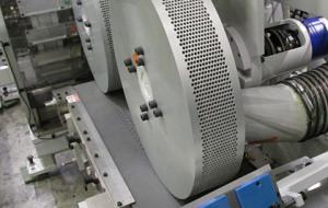
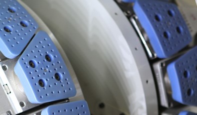
The thermal bond unit consists of two heated rolls. Typically, one roll is patterned and the other is smooth. Air cylinders may be used to apply minimal pressure between the anvil and the pattern roll.
The ultrasonic bond unit consists of an anvil roll and stationary (or rotary) ultrasonic assemblies. The ultrasonic assembly bonds multiple layers of the product together by use of vibration and pressure. The product web wraps the patterned anvil roll as it passes under the head of each ultrasonic unit. Bonding takes place when the head and anvil compress the product web.
Hot-melt glue is loaded into a heated tank. The glue is melted and pumped to an applicator head. In many cases, the glue head is allowed to contact the web during the glue application. The glue applicator may include electronics to apply the glue in a preset pattern.
The mechanical bonding unit consists of two rolls. Usually, one roll is patterned and the other is smooth. Air cylinders, or other methods, may be used to apply the required bonding pressure between the anvil and the pattern roll.
Since 1932, Curt G. Joa, Inc. has been the leader in engineering and building custom machines for the disposable market.

With operations in Wisconsin, Germany and India, Joa serves customers throughout the world.